Repair notes for various computer equipment
AlphaServer 1000A Storage Bay Door Button
The button of the storage bay door is broken and now the storage bay door is constantly open.The "hinges" of the bay door button are two small plastic pins and are not very strong. After some time pushing the bay door button the pins broke and the button can no longer hold the storage bay door in its place (i.e. swings open every time). So, I made holes in the face plate where these plastic pins used to be and inserted an iron pin which would hold the bay door button in place and thereby the storage bay door.
- For the upper hole I used the blade of a small hacksaw to create a hole of 2 mm. For the bottom hole I drilled a hole of 3 mm. This was a bit tricky because the location of the bottom hole is difficult to reach with a drill, so I carefully drilled from different angles until the hole was deep enough (I actually drilled all the way to the horizontal air gap of the face plate). See picture of holes.
- Next, I took an iron pin of about 3.5 cm long and 2 mm thick. Bend half a centimeter at a right angle to make a handle of this pin. Insert the handle in the drilled holes to see if it fits. Also check whether the handle has a clear path from the upper hole down through the bottom hole of the bay door button; remove any plastic material from the button that's in the way of the handle.
- Finally, put the bay door button into the face plate along with the spring. Push down the spring and insert the handle in the holes (i.e. the drilled holes, the holes of the button, and the holes of the spring). This may be a bit of tinkering, but when succeeded the bay door button will be rock-solid.
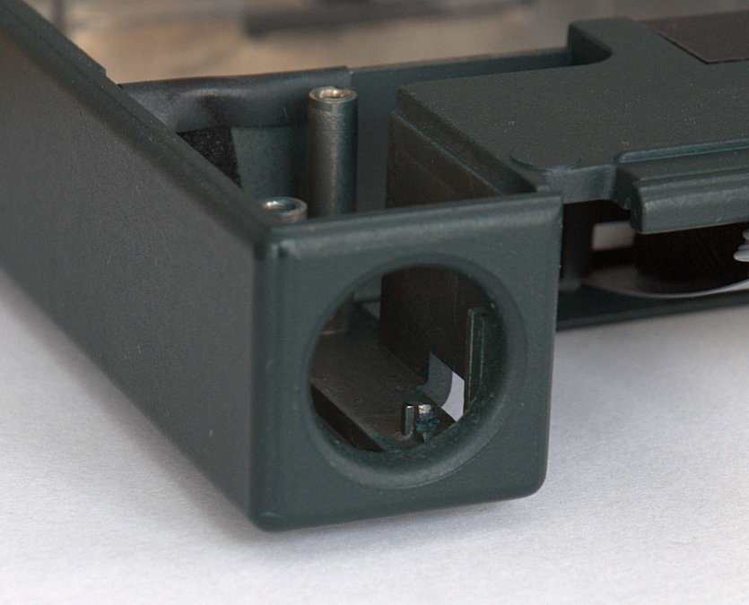
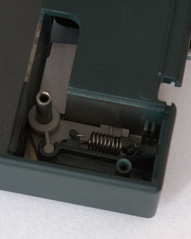
DECpc Trackball Eject Mechanism (1)
The DECpc laptops have a funny mouse pointer assembly (it's actually called the Trackball). The trackball assembly is mounted on a metal sheet which is curved upwards at the end of the trackball assembly. When the trackball is unused it is retracted in a small cavity of the system casing. In order to use the trackball, the user pushes the eject button near the trackball assembly causing the assembly to pop out of the cavity. The trackball is then positioned along the side of the laptop casing.Unfortunately, handling the eject button to hard may break a plastic pole of the eject mechanism. Attached to this plastic pole is a spring which (indirectly) holds the trackball assembly in the aforementioned cavity. If the pole breaks, there's no tension to the spring and the trackball assembly contineously pops out. If you still have the broken piece of the plastic pole, you can try glue to fix it. If the pole is gone, you can try to make a small cut in the stub of the pole. Next, you can hook the spring to the stub and ensure the spring aligns with the cut you made. There's enough room for the spring to hook to the stub. The eject mechanism should now be working again.
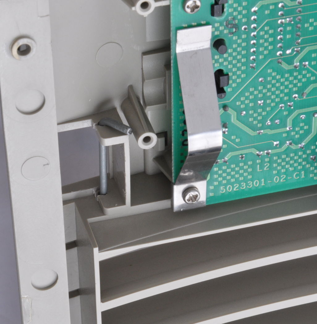
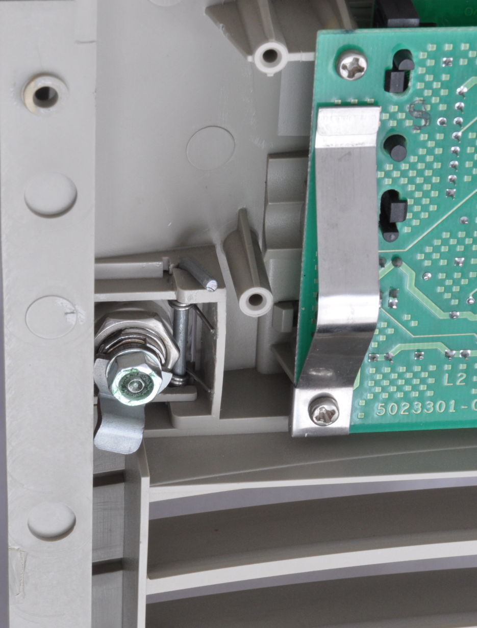
DECpc Trackball Eject Mechanism (2)
Someone has been rocking the trackball assembly too hard, so now the metal strip attached to the trackball no longer ejects properly. The metal strip is held in position by a plastic cover. This plastic cover is attached to the base chassis by a number of tiny nails sticking through small holes in the base chassis. The nails are made of plastic and they seem to be molten to the plastic cover. Strong enough for normal use, but not always.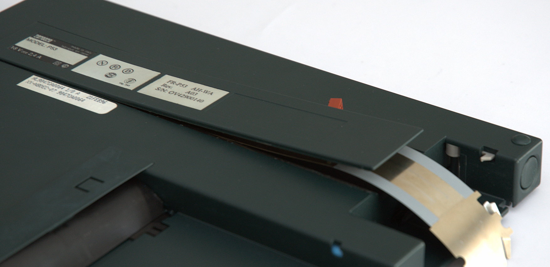
So, I drilled some holes in the plastic cover, matching the aforementioned small holes in the base chassis, and used tiny screws, washers, and nuts to tighten the plastic cover to the base chassis. The screws and nuts need not be too tight else the metal strip of the trackball assembly won't move smoothly.
HSG80 Resurrection
I used theCONFIGURATION RESET command on two HSG80 controllers in
an ESA12000 array. Apparently you shouldn't do that because it renders the
maintenance port inoperative and you loose the ability to configure the
controller. Admittedly, the
HSG80 CLI Reference Guide
does mentions the command disables communication between host and controller.
The controller does seem to be operational given its flashing Reset button/LED,
but you just cannot access it. So, I picked another HSG controller which was
working but had a slightly higher firmware version. I used the FRUTIL
utility and tried to remove & re-install the "dead" HSG controller into the
ESA12000 array. Too bad, the firmwares were not compatible (OCP Code 3D, "NVPM
structure revision greater than image's."). I guess this error relates to some
data structure in the non-volatile memory of the controller. Suffice it to say
that the "dead" controller was now really dead.
Clear NV-memory and Restore Maintenance Port
FRUTIL utility on the surviving
controller to re-install the "dead" controller should bring it back. You may
need use the SET FAILOVER command or the
SET MULTIBUS_FAILOVER command to get the controller configuration
correct.
23-DEC-2023 — I guess I was lucky when I tried the above procedure in the past. Recently tried it, but it didn't bring back the maintenance port.
Next, it could be that the resurrected controller now has lost its serial number and its hardware revision number. I'm not entirely sure about this, but the controller may signal an Error 4090 ("Module has invalid serial number."). In this case the serial number has been reset to "CX20100000" while the hardware revision is set to "0000". A command exists to correct these numbers. I've used the following commands on the resurrected controller to restore its serial number:
SET NOFAILOVERorSET NOMULTIBUS_FAILOVERSHUTDOWN OTHERDANGEROUS X SERIAL="<serial-number>" PREDANGEROUS X HARDWARE=" <hw-rev>"- Restart
OTHERcontroller. SET FAILOVERorSET MULTIBUS_FAILOVER
DANGEROUS
command above should do the trick. The hardware revision can be found on a
label on the PCB. Also, before using the command to set the serial number, you
can postfix the command with a question mark; there are some more options.
Replacing Coin Cell
I've also encountered an OCP Code 30 ("The JSRAM battery is bad."). It appears this refers to the coin cell mentioned earlier. The coin cell is a 3V lithium cell (CR2032) and in order to replace it, you need to remove the top cover of the HSG controller. You can follow these steps:- Remove the GLM access door from the top cover as well as the controller's program card. Strictly not necessary, but removing these two items makes removal of the top cover somewhat easier.
- Remove the left and right handle of the controller. You can use something like a small nail and a pipe wrench to push the captive pin out of the handle.
- Remove the 5 screws holding the PCB and the top cover.
- Gently lift the top cover such that the thermal pad of the i960 policy processor comes loose.
- Slide the top cover off the PCB.
- Replace the coin cell which is located behind the reset buttons.
-
Re-assemble the controller and use the
FRUTILutility to re-install the controller (see above).